LED Flashlight


Click Link(s) Below for Latest Update


Parts/Spice File Links
FPGA Board LED Problem
Funny Filter Response


Goal

Design and build a color accurate LED flashlight for high end applications.

Example Block Diagram

Image

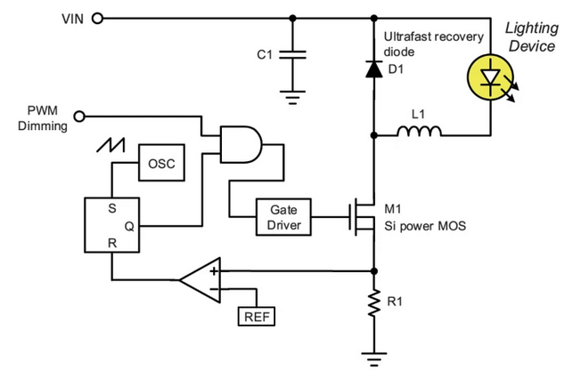
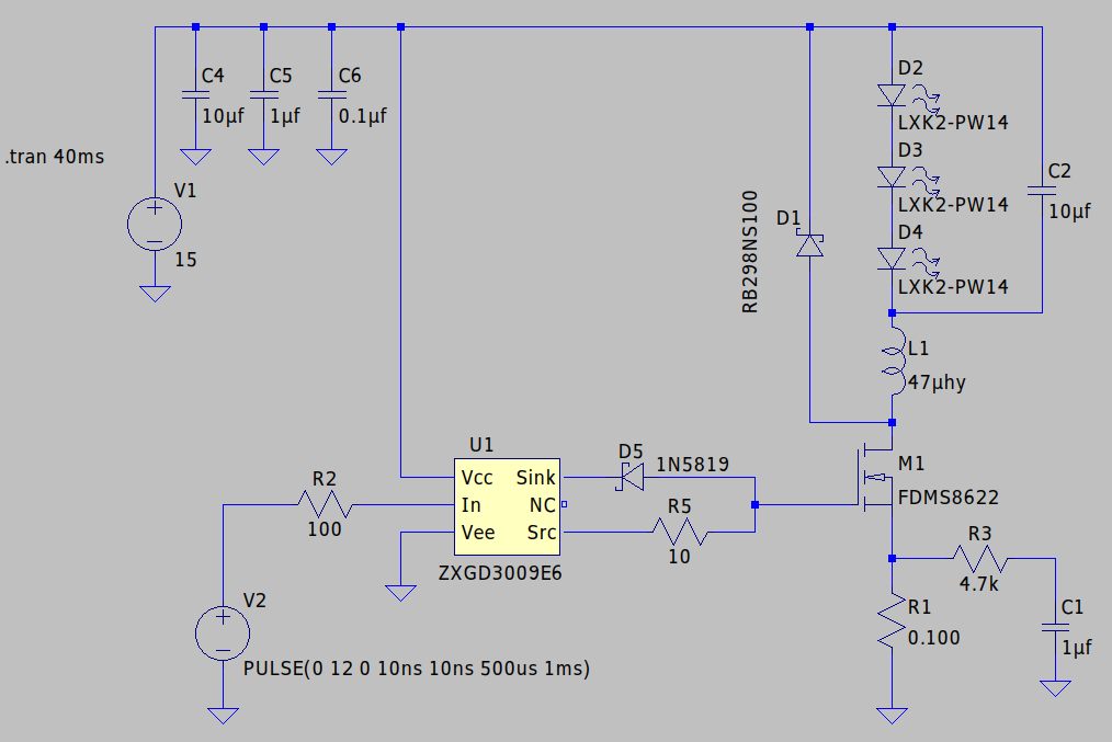
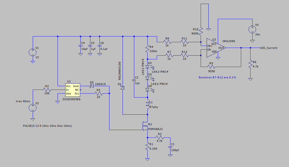
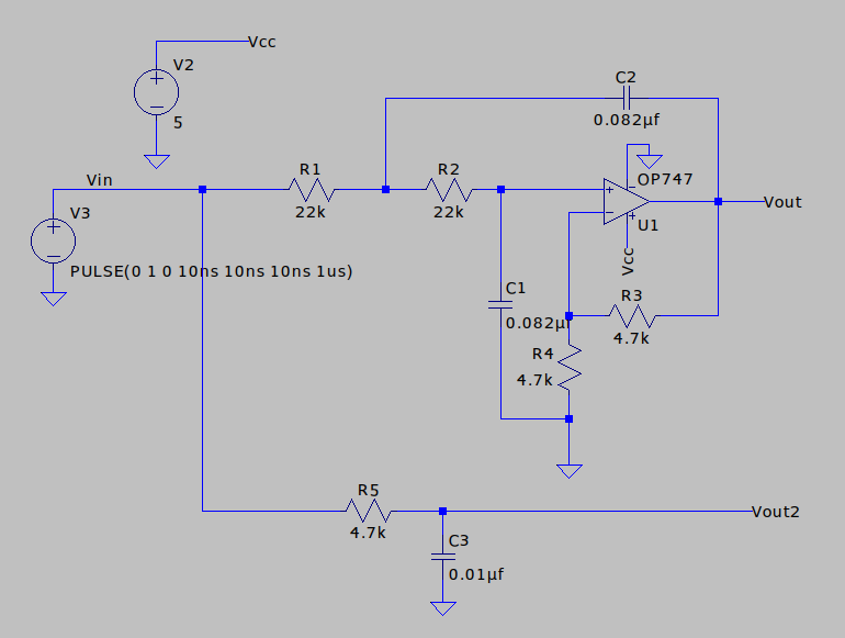
At right is a simple LED driver with a simple digital control system. It's documented here.
It appears to be a current controlled topology. It's constant frequency and turns off when the sense voltage (driven by the output current) exceeds $V_{ref}$.

The eventual goal is to replace much of the digital side with an FPGA, but it's illustrative here to get a general idea of a simplified control loop.

It uses a GaN Mosfet, EPC8010 datasheet and runs about \$2 in 100 quantity. This part allows very high frequency switching.

For efficiency reasons D1 should probably be replaced by another Mosfet making it a synchronous switcher.

Background Material

Here is a mind boggling paper on control techniques using state space .

Also here is a set of videos from TI

Seminar videos from Analog Devices on switchers. (Maxim is now part of Analog Devices).

Additions

Bootstrapping

An additional supply (perhaps just a capacitor) to supply the gate drive with a high drive voltage.

Synchronous Mode

This uses a Mosfet to replace D1 (the catch diode) resulting in much less power loss since the $\small RDS_{on}$ is much smaller than even a schottky diode.

Protection

Image

Example of a 'protection IC'. This gives a naive implementation that can be used as a guide.

Video for understanding the specifications of protection ICs.

Herman Gate Driver Design

Image

This is Herman's P-Channel high side gate driver, part number IRS10752LTRPBF datasheet. We are using a low side driver so this is to see a gate driver in situ. We will need a similar compensation network before the gate.

Image

This is the gate driver power supply. It's a bit tricky with two 12 volt regulators, part numbers L79L12ACUTR datasheet, and L78L12ACUTR datasheet; positive and negative regulators.

OK! Let's Start Designing

High Side Current Sense

Image

  After a discussion with Herman, putting a small resistor (100mOhm) in the Source to ground leg is Ok.
It will only raise the gate voltage requirement a small amount.

The circuit is from a TI App Note. High side sensing has noise advantages also I believe (I'll check with Herman) that we can't use low side because the gate drive would have to go through the sense resistor which would limit the current! Something we are desparately trying to increase.

Here's a shi-shi-foo-foo (albeit excellent) op amp, OPA2991IDGKR datasheet

Low Side Gate Driver

Fundamentals of Gate Drivers .. 48 pages!

Low Side Gate Driver with Totem Pole. We don't want a totem pole. There are issues. See Doc.

Choosing Parts

Type Part Manuf Datasheet Source Price (100) Spice Comments
FET RQ6E045TM Rohm (datasheet) Digikey \$ 0.44 model Next Try
FET CSD17484F4 TI (datasheet) Mouser \$ 0.65 model Excellent
FET FDMS8622 OnSemi (datasheet) mouser \$ 0.99 model Slow?
Current Sense INA180A4 / B4 TI (datasheet) Mouser \$ 0.38 model Cheaper than Discrete
Current Sense INA180A2 / B2 TI (datasheet) Mouser \$ 0.38 model Cheaper than Discrete
Current Sense INA180A1 / B1 TI (datasheet) Mouser \$ ?? model Cheaper than Discrete
Gate Driver FAN3111E Fairchild (datasheet) Mouser \$ 0.67 model.zip) Looks good
Gate Driver IRS44273L Infineon (datasheet) src price Y Need more info
Gate Driver ZXGD3009W6 Diodes Inc (datasheet) src price model Need more data
Gate Driver NCP51100 N
Gate Driver TPS2819QDBVRQ1 N
Gate Driver TPS2816 N
Gate Driver IRS44273L Infineon (datasheet) src price Y more info
OpAmp OPA2990IDR TI (datasheet) Digikey \$ 1.14 model App Note Recommends
OpAmp BU7487 ROHM (datasheet) Mouser \$ 0.84 model Quad Opamp
OpAmp MC33274 OnSemi (datasheet) Mouser \$ 0.77 model Quad Opamp

LTSpice

Image

I will send the .asc Sim file to you via email.

The image here is for reference.

Below is what you have to do to get it running.

To add the FDMS8622 FET model to LTSpice (spice here) follow these instructions.

To add the ZXGD3009W6 Gate Driver model (spice here) to LTSpice follow these instructions

Sim Results 10us/10ns

Image

Image

Design High Side Sense

Image

Advantages ..

Here's another App Note
Here's an intro into using the inductor's series resistance as the sense resistor. This is frowned upon when using the technique in the previous app note.

Discrete Design

Note ..

R1 and R4 should be matched, as well as R2 and R3 for improved accuracy.

Now let's look at the common mode voltage ..

From the App note has an output voltage calculation including the error from offset voltage and shunt resistance.

Vo = (Gain+1) Voffset + GainVshunt

If the voltage across the shunt is 200mv, the offset error and shunt resistance cause an error shown below.

The error would be about 0.33 percent if the shunt resistor was 0.2 ohms.

Integrated Design

Here's an IC .. INA180A4 (200 gain) or the INA180A2 (50 gain) from TI ... \$ 0.38 in hundreds (priced increased to $ 0.41). Uses either a 5V or 3.3V supply.

See the parts table above for details.

The 'A' in 'A4' is the package type. The '4' in 'A4' is the gain, here 200V/V

Mouser has no stock

The chip has matched resistors (likely) , a known gain, a 3.3V supply, and it's cheaper than just the opamp unless I go reallycheap. It claims 350Khz response. I'm not sure how much we can calibrate out (unless we do a table). The chip should be more well behaved if it matches the internal resistors. We can probably go for a 100mOhm shunt instead of a 10mOhm one and go for the 'A3' part (gain.

TI Does it Again ....as long as the shunt common-mode voltage is greater than VS when the device is powered up ... It does some sensing at power up and modifies it's behavior .. dunno how important that is yet.

Determine Gain Required

Maybe the sweet spot is 30 milliohms with a gain of 50.

Image

For fun here's what the discrete version looks like ...

The integrated version doesn't have the 4 resistors around it, and a 5V or 3.3V supply instead of the 24V one.

Cheap Dual Design

TSM104 is a cheap quad op amp at $ 0.61. Could be good but no model! This would make, with two sensors per channel about \\$ 0.30.

After a phone conversation with Jay we decided to just use the INA180 .. with two chips per channel it's a bit expensive but we can get it and it has a model ...

LTSpice Info

LTSpice .step and .meas, for efficiency, and normal

.step param Iload .2 1.2 .1 .tran 0 2.1m 2m startup .meas Pin AVG -V(IN)I(V1) .meas Pout AVG V(OUT)I(I1) .meas Eff param Pout/Pin

Ctrl+L hotkey to see log

Schematic Portability

I found another way to do it but really the easiest way is to do what we have been doing.

FYI here's the workaround ..

Idea(s)

Linearity Sim Results

LP Filter Design

Sallen–Key 2 pole low pass filter.

Image

Image</

Let's try some isolated pulses and compare the filter output to a simple single pole RC filter (see schematic above).

Let's try some pulse trains .. 10% duty cycle at various frequencies

Below is 1khz pulse train with 10% duty cycle.

Image</

Below is 10Khz pulse train with 10% duty cycle.

Image</

Below is 100Khz pulse train with 10% duty cycle.

Image</

Below is 1Mhz pulse train with 10% duty cycle.

Image</

Below is a one percent duty cycle at one megahertz ..

Image</

Below is the above plot zoomed in to see details.

Image</

Image

Crap Opamp Filter Response

Image

Good Opamp Filter Response.

I don't think this is right!

I'm digging

LED Problem

Here's the datasheet

Spec Type Red Grn Blu
Avg Vf 1.9V 2.9V 2.9V
Max Vf 2.5V 3.6V 3.6V

The above table is at 5ma.

Image

Here's the Green LED Drive from the Nordic.

It's strange. The specs say that the Blue and Green LEDs should have the same $V_f$ but the waveforms are substantially different.

Is there a difference in the pin drive levels?

Flashlight Test

Image

Set PWM to 100us period 1us pulses.

Neither sensor can see 3.6ma ..

I'll work on it.

Problem above was apparently due to a bad op amp model.

Let's try another op amp .. MC33272 .. (see parts table above).

Funny Two Pole Filter

Image

Image

Why does the response go up past 30Khz?

Here is the datasheet

Supposedly the GBP is 24Mhz and I've got a gain of two.