Photo Booth Project

In [1]:
:opt no-lint

Feb 22, 2023 Update

Executive Summary

  • USB-C delivers 3.2A at 5V
  • LED Driver delivers 4.2A at 5V
  • Thermal rise after 5 min about 24 degC which is crazy good. Modelling said it would be at least a 30 degC rise with a 11 square inch copper plane surrounding the chip with vias to the bottom layer, which we don't have.. Perhaps a longer time is needed to reach equilibrium. Your experiments will tell.

Details

In [14]:
import Text.Printf

calcSpecs :: Float -> Float -> Float -> Float -> IO()
calcSpecs supIOut iOut  aTemp dTemp = do
    let usbPwrIn = 12.0 * supIOut
    let usbPwrOut = 5.0 * iOut
    let usbEff = usbPwrOut / usbPwrIn
    let heatW = usbPwrIn - usbPwrOut
    let degCperW = (dTemp - aTemp) / heatW
    
    printf "Current Out %5.2f amps \n" iOut
    printf "USB-C Efficiency %5.2f \n" usbEff
    printf "Heat %5.2f watts\n" heatW
    printf "DegC per Watt %5.2f \n" degCperW

USB Efficiency

In [15]:
calcSpecs 1.50 3.23 18.0 43.0
Current Out  3.23 amps 
USB-C Efficiency  0.90 
Heat  1.85 watts
DegC per Watt 13.51


LED Driver Efficiency

In [16]:
calcSpecs 2.0 4.3 16.0 43.0
Current Out  4.30 amps 
USB-C Efficiency  0.90 
Heat  2.50 watts
DegC per Watt 10.80

Feb 18, 2023 Update

  • Applied a 1 amp load on U4. Started at low current to prevent catastrophe
    • Worked Fine, 5V out.
    • Temp rise was 14 deg F after about 3 minutes.
    • Switching frequency 714 Khz .. per spec.
    • Noise level roughly 200mv at 1 amp load.
    • Efficiency = 5.0 / (12.0 * 0.45) = 93% (measured with Fluke 87)
  • Connect 1 amp load to USB-C (5V was supplied to a portable led work light)
    • Worked fine.
    • Approximately same heating level as above.
    • Not sure if there was negotiation or it was just a 5V default.

Monday I am expecting an adjustable 4 amp USB load, and a variable load for the LED regulator. I don't have a way to force voltages other than 5V from the USB-C. I did check into it but the price for test boxes varies between \$1,200 and \$15,000.

In [5]:
-- Rough Thermal Calcs

tJA  = 15 -- degC/Watt ... Chip mounted on JESD51-7 board (approx 7cm x 11cm)
tA   = 25
vOut = 5.0
iOut = 4.0
eff  = 0.8

-- If efficiency is 80% into a 20 watt load 
-- then the power in the switcher is the total
-- power loss minus the inductor IR loss,

pDiss = (vOut * iOut) * (1 - eff) - (iOut * 10e-3)
printf "Buck Convert Power Loss = %5.2f watts" pDiss
incrT = tJA * pDiss + tA
printf "Temp increase at full power = %5.2f degC " incrT
putStrLn "But our layout isn't as good as the JESD51-7"
putStrLn "Max recommended temperature 150 degC"
Buck Convert Power Loss =  3.96 watts
Temp increase at full power = 84.40 degC
But our layout isn't as good as the JESD51-7
Max recommended temperature 150 degC

Feb 17, 2023 Update

  • Found several discrepancies between the board schematic and the typical application shown in the schematic with the exact required specification; i.e. 12V in at 6A. I know the spec is less than 6A but margin is prudent.

RefDesign

Executive Summary

  • Both swithcers are now working, producing 5V with no load. For details see below.
  • I'm still a bit worried about the inductor choice so I haven't yet checked the 4A max.
  • I have not tested the USB-C driver. I'm waiting for a USB-C tester which should arrive today. The specs of it weren't clear but I'm hoping that it will check all possible voltage / current outputs. If you have a tester let me know.
  • There are still things to do ..
    • Verify max loads (mentioned above)
    • Verify thermals for switcher and inductor. What is the environment for the board .. shirt sleeve? ... a mobile trailer in the Arizona desert? This can be important in determining the thermal design.
    • Verify USB-C for all voltages / currents (also mentioned above)
    • Input protection? ESD, Spikes, etc.
    • Input voltage tolerance. I was wrong before about the USB-C chip making 24V problematic. It's powered by the switcher not $V_{in}$. However, the absolute max for the switcher is 26V. So a typical off the shelf 24V supply can be 26.4V (+10%) exceeding this. If you supply the supply (pun intended) then you're fine.

Details

  • PG (power good) is tied to $V_{in}$ but datasheet says it must not go above 4.5V. This was the 'LED' issue. The switcher is has it's own internal LDO that supplies 3.6 volts to the outside world. This should be used for the pull-up source as shown above but without the LED ..
    • The MODE pin is floating in the reference design, indicating PFM, Ultrasonic Mode. On your board it's tied high indicating forced PWM mode .. This should be Ok
    • R6 should be left open. There is an error in the datasheet indicating that the internal pull-down resistor is 600K. It's a lot lower. So, stuffing R6 caused the EN (enable) pin to be a logic low, keeping the chip from turning on. The board design would have been Ok if the datasheet was correct. See design verification below.
    • LED circuit should be changed to the VCC source in series with a 330 ohm resistor, connected to the switcher's VCC pin. The resistor value can be changed until you get the desired brightness.
    • C1, C17 - the previous rework is fine.

Design Verification Feb 15

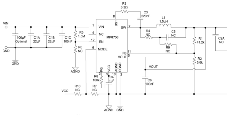
To make sure we didn't have problems below is are some rough design calculations per the sometimes correct datasheet.

In [6]:
import Text.Printf

-- We don't want to blow up the chip
-- so compute vEN to be sure that
--     4.0 > vEN > 1.4
vIn = 12
r6 = 300e3
pullDown = 600e3
rp = (r6 * pullDown) / (r6 + pullDown)
vEN = (vIn * rp) / (1.5e6 + 600)
printf "vEN at 12V -> %5.2f" vEN
printf "vEN at 24V -> %5.2f" (2*vEN)
vEN at 12V ->  1.60
vEN at 24V ->  3.20

r6 at 300k yields a good vEN for 12 and 24v

In [7]:
vRef = 600e-3
r1 = 41.2e3

-- Calculate R2 for output volage of 5V
r2 = (vRef * r1) / (5.0 - 0.6)
printf "r2 = %5.2f" r2
r2 = 5618.18

Board values for FB resistors are correct for Vout is 5v.

In [8]:
vPG = 0.4 -- at I = 4ma
vCC = 3.6 -- nominal

Inductor Choice

In [9]:
fSW = 700e3
deltaI = 2.8 -- 30% of output current
vOut = 5.0
vIn = 12.0
indL = (vOut/(fSW*deltaI)) * (1.0-(vOut/vIn))
printf "L -> %5.2e" indL
L -> 1.49e-6

This means that the ripple current will be 2.8 amps

Peak Inductor Current

In [10]:
iOut = 6.0
iPeak = iOut + (vOut / (2.0 * fSW * indL)) * (1.0 - (vOut / vIn))
printf "Ipeak -> %5.2e" iPeak
putStrLn "This is below the max switch current of 10A"
Ipeak -> 7.40e0
This is below the max switch current of 10A

Power Good Circuit

The VCC output is 3.6 volts and the $V_f$ of the LED is 1.8V so the series resistor should be approximatly,

In [11]:
rLED = (3.6 - 1.8 - 0.4) / 4e-3
printf "LED series resistor -> %5.2f" rLED
putStrLn "So make it 330 for about 4ma"
LED series resistor -> 350.00
So make it 330 for about 4ma

Feb 9, 2023

Talked with Joey.

  • Received Initial spec, schematic, gerber, BOM, and board images.
  • Downloaded relevant datasheets
  • Reviewed USBCtllr, MOSFets, Switcher IC datasheets
  • The USB-C interface appears quite simple which makes sense as there is no data transfer, only power.
  • Power input protection (12V) is almost non-existent. No surge protection, and no ESD protection.
  • Circuit isolation from the power input is also missing which may cause FCC conduction approval issues.
  • Chip choices are appropriate.
  • PCB trace sizes appear to follow good design practices.
  • Fab may not have undergone normal electrical test. This increases the possibility of PCB errors.
  • The LED behavoir mentioned makes no sense and initially implied that U4 was reversed. Subsequent conversation with Ryan show this is not true. This is currently the biggest mystery.
  • A rough design was done to determine the inductor specification per the MPS website.The inductance indicated was 15 times larger than the one on the PCB (22uhy vs 1.5uhy). The physical size was also larger (roughly 13mm square vs 9mm square). The inductance and physical size could indicate a potential saturation issue (saturation = poof). A deeper dive into the inductor spec will be useful. Unfortunately a PSpice model is not available for this switcher IC.

Datasheets

USBChip

Switcher

FET

USB Connector

Inductor

LED